
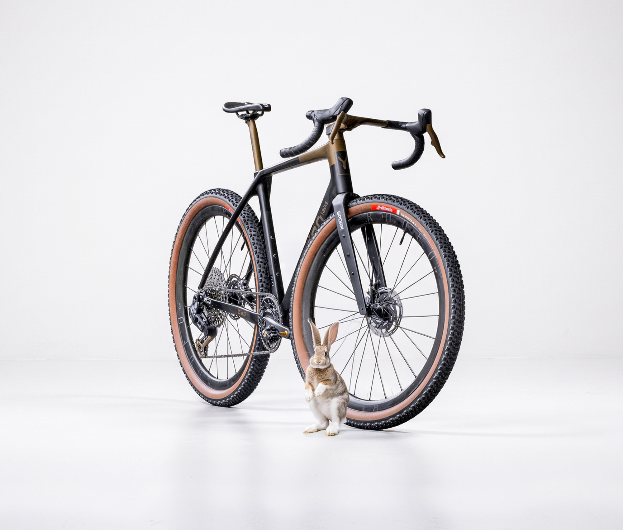
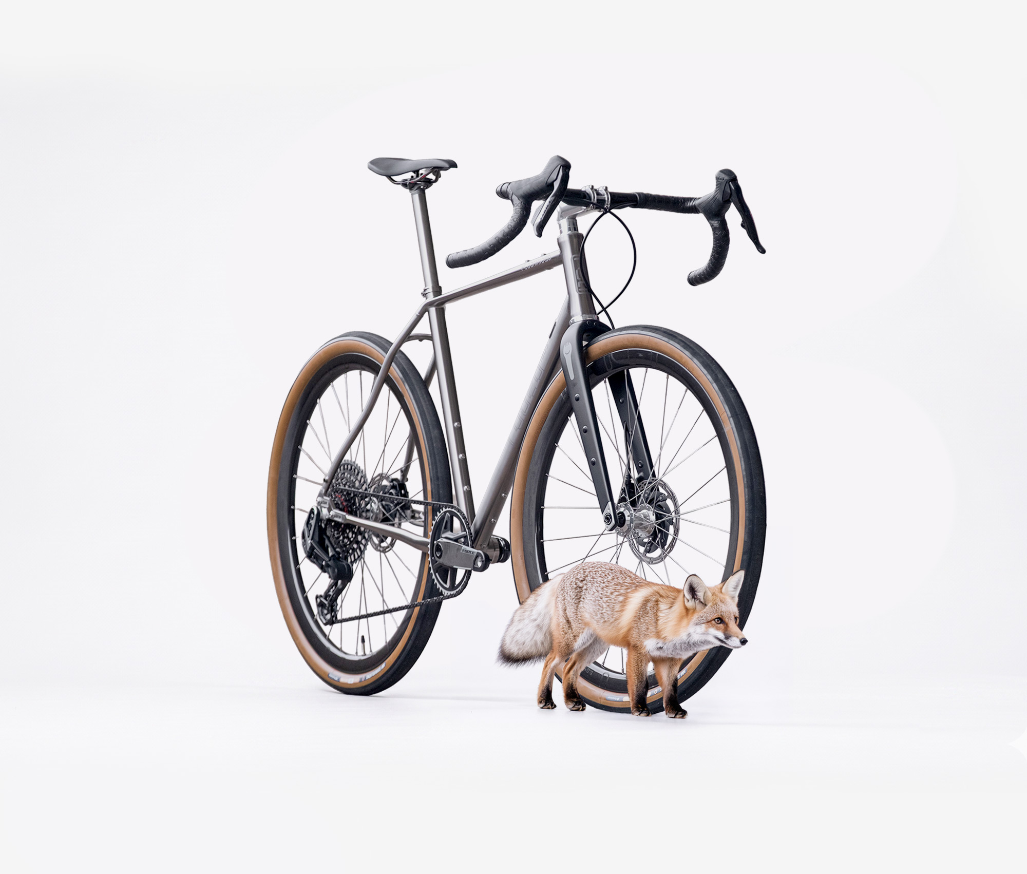
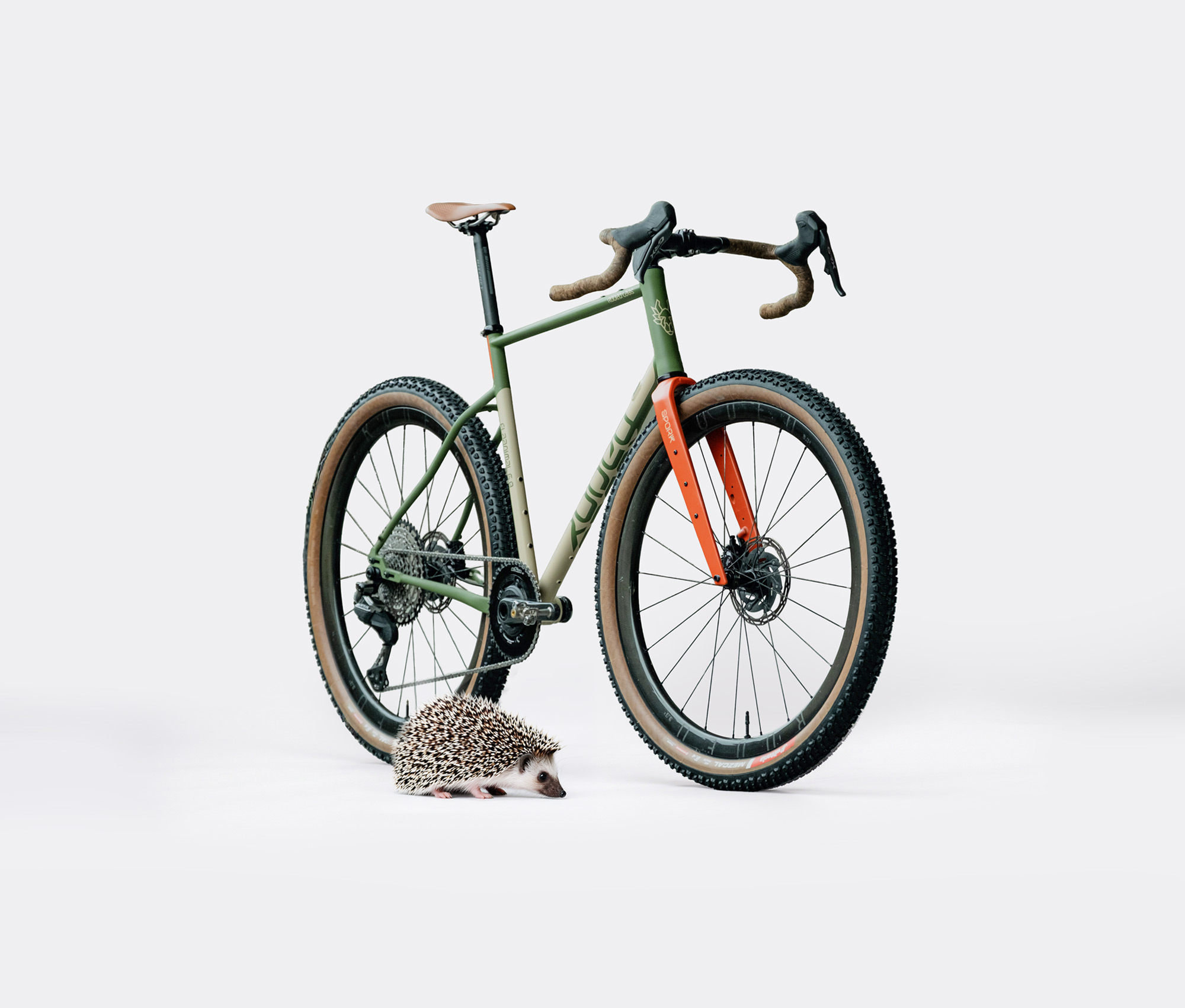
Flaanimal 6.0 Steel / Titanium – Owner’s Manual
Rodeo Labs Flaanimal 6.0 Owner’s Manual & Technical Installation Guide
1. Front Matter & Model Identification
Model Coverage: Flaanimal 6.0 Titanium (3/2.5 Ti) & Flaanimal 6.0 Steel
Document Version: v6.0-2026.1
Rodeo Adventure Labs, LLC – Ride. Explore. Create. Since 2014.
Welcome to the Rodeo Labs family. The Flaanimal 6.0 is a maximal expression of adaptability, durability, and utility woven into a high-performance adventure frameset. This technical manual provides precise step-by-step assembly instructions, critical engineering constraints, and industry-standard safety warnings to ensure your bike operates safely and flawlessly for a lifetime of exploration.
| Owner Record Field | User-Recorded Value |
|---|---|
| Frame Serial Number (Stamped underneath BB shell) | ____________________________________ |
| Purchase Date | ____________________________________ |
| Authorized Dealer / Builder | ____________________________________ |
Notice: Component Documentation. This manual governs only frame-specific and fork-specific components manufactured by Rodeo Labs. For third-party components (e.g., SRAM, Shimano, Campagnolo, White Industries, Wolf Tooth), always consult the original manufacturer\’s documentation for installation sequencing and torque specifications.
2. Safety & Structural Usage Classifications
ASTM F2043 Classification: Condition 2. The Flaanimal 6.0 and its accompanying Spork fork are engineered and tested to satisfy standard load protocols for rough trails, unpaved surfaces, and gravel courses, including drops and ledges of less than 24 inches (61 cm). It is explicitly not designed for aggressive downhill riding, dirt jumping, or aerial acrobatics.
ISO 4210 Certification: Fully tested and certified under ISO 4210-2 requirements for Mountain and Racing Bicycles, confirming structural capability under demanding off-road conditions.
⚠️ [WARNING]: TOTAL SYSTEM WEIGHT RESTRICTIONS
The maximum allowable combined weight for the rider, apparel, and all cargo/luggage is strictly limited to 280 lbs (127 kg). Exceeding this weight threshold subjects structural elements to stress loads beyond engineering design margins, risking catastrophic material fatigue or sudden mechanical failure. Warranty is also voided if ridden above allowable limit.
3. Technical Specifications
| Frame Constant / Interface | Technical Specification Requirement |
|---|---|
| Bottom Bracket Standard | T47 Inboard Threaded (85.5mm shell width) |
| Headset Configuration | 44mm Inner Diameter |
| Seatpost Diameter | 27.2mm ID (Titanium Seatpost Collar Outer Diameter: 31.8mm, Steel is 29.8mm ) |
| Rear Axle Interface | 12mm x 142mm Thru-Axle (1.0mm thread pitch, 163mm total length) |
| Rear Brake Interface | Flat Mount (160mm rotor native configuration) |
| Max Tire Clearance (700c) | 700c x 55mm (Requires 4-6mm mud/flex safety clearance) |
| Max Tire Clearance (650b) | 650b x 2.4 inches (Requires 4-6mm mud/flex safety clearance) |
| Drivetrain Compatibility | 1x Mechanical/Electronic, 2x Mechanical/Electronic, Singlespeed, SRAM Full Mount (T-Type native), Backwards compatible via UDH Hanger |
4. Assembly & Component Installation Guide
4.1 The Lockjaw-2 Slider Dropout System
The Lockjaw-2 system uses precision CNC-machined metal teeth that interlock with corresponding toothed stainless steel compression plates. This mechanical interface distributes acceleration and braking forces evenly, drastically minimizing the clamping torque required to prevent axle movement while offering complete adjustment over wheelbase length and singlespeed chain tension.
4.1.1 Hardware and Torque Requirements
- Fixing Bolts: M6 x 14mm Titanium Fixing Bolts (Quantity: 4)
- Required Tooling:T30 wrench / driver bit.
- Torque Specification: 11 Nm (97 in-lbs) via a calibrated torque wrench. Never exceed 12 Nm.


4.1.2 Drivetrain Adjustments & Chain Sizing Notes
- SRAM T-Type (Transmission) Direct Mount Compatibility: The frame profiles are designed natively to accept direct mount rear derailleurs. No UDH hanger is used for T-Type setups.
- Standard Derailleurs: Install a standard SRAM UDH Hanger into the sliding dropout for non-Direct Mount builds.
- Chain Length Modification Warning: SRAM’s online chain length calculators assume a maximum chainstay length of 450mm. The Flaanimal 6.0 features adjustable stays extending up to 465mm. If you configure the Lockjaw-2 sliders at or near their maximum rearward extension, you MUST add one full link assembly (one inner link and one outer link) beyond the length prescribed by the standard 450mm calculation to avoid catastrophic failure at full drivetrain wrap.
4.1.3 Precise Step-by-Step Slider Alignment Procedure
- Place the non-drive side slider (flat mount brake face) into the inner frame slot from the inside of the frame profile.
- Slide the non-drive side unit to your desired wheel-base location based on tire size or preferred handling geometry, and snug the two fixing bolts down hand-tight.
- Insert the drive-side slider loosely into the opposite frame slot. Thread its two M6 fixing bolts by hand so the slider plate can move freely forward and backward.
- Mount the rear wheel into the frame slots, slide the 12mm thru-axle completely through the assembly, and torque the axle to its tight operational spec using the Clever Lever tool. Technical Logic: Fully tensioning the axle forces the loose drive-side slider into absolute parallel alignment with the fixed non-drive side slider automatically.
- With the axle fully tensioned, use a calibrated torque wrench to tighten the four M6 Titanium fixing bolts to exactly 11 Nm using an alternating cross-pattern. Be sure to check for proper groove washer engagement with Lockjaw teeth profiles
⚠️ [WARNING]: SLIDER SLIPPAGE RISK
Failure to follow the exact axle-first tightening sequence or failure to achieve the required 11 Nm torque on the Lockjaw-2 fixing bolts can cause the sliders to slip out of alignment under heavy braking or acceleration. This will may result in an immediate rear wheel jam, catastrophic frame damage, or severe loss of rider control.
4.2 The “Keg” T47 Inboard Bottom Bracket & Cable Routing
The custom “Keg” bottom bracket shell offers a vast internal chamber to guide brake hoses, shift housings, and electrical wires internally through the frame without exposing them to exterior trail debris or water damage at the bike’s lowest physical profile…

⚠️ [WARNING]: MANDATORY USE OF SPINDLE PROTECTION SLEEVE
You MUST install a protective spindle sleeve, typically metal or plastic, between the two bottom bracket cups to prevent spindle contact with brake hoses, cable housing, or electrical wires . Failure to install this sleeve allows the rotating crankset spindle to make physical friction contact with internal lines. Continuous abrasive spinning WILL saw through hydraulic brake hoses and electrical wires, inducing complete brake system failure or shifting blackouts.
| Line / Cable Profile | Internal Routing Pathway | Technical Execution Note |
|---|---|---|
| Rear Hydraulic Brake Hose | Contours completely BELOW the spindle sleeve. | Do not cut taut; allow slack for the hose to follow the shell curvature. Pass into non-drive chainstay. |
| Rear Mechanical Shift Housing | Contours completely BELOW the spindle sleeve. | Guides out from the down tube and transitions directly into the drive-side chainstay. |
| Front Derailleur Cable Housing | Routes ABOVE the spindle sleeve. | Utilizes the internal CNC BowTie cutout to smoothly exit the dedicated port on the back of the seat tube. |
| Mechanical Dropper Post Housing | Routes ABOVE the spindle sleeve. | Feeds cleanly through the CNC BowTie channel and runs vertically straight up into the seat tube cavity. |
4.2.1 Shimano Di2 Wiring Optimization Protocol
- Position the Di2 battery securely inside the seatpost or seat tube using an approved rubber or foam retention sleeve.
- Route the front derailleur wire through the lower seat tube port directly to the battery.
- Guide the rear derailleur wire underneath the crank spindle sleeve, traveling internally through the drive-side chainstay until it exits near the dropout.
- Critical Routing Security: Upon exiting the driveside chainstay port, loop the Di2 wire cleanly around the outside profile of the rear dropout. Secure the wire firmly using a housing routing clip anchored directly to the rear fender frame mount eyelet. This eliminates loose slack and completely insulates the wire from being sheared or caught by a moving chain, cassette, or trail brush.
4.3 Headset Installation and Cable Integration
The Flaanimal 6.0 Titanium features a beautifully custom hourglass-shaped head tube. While visually elegant, the changing inner diameter prevents standard straight headset cup removal tools from seating securely against the lip of the cups.
ℹ️ [NOTICE]: HEADSET CUP REMOVAL TOOLING REQUIREMENT
To safely remove pressed headset cups from the hourglass head tube without scarring the titanium bore, you must install an easily available specialized C-clip snap ring along the inner rim of the headset cup. This creates an artificially wide shelf for standard cup removal tools to grab onto. Rodeo Labs stocks these clips (McMaster-Carr Part 98455A725 functional equivalent) for specialized shop use.
4.3.1 Headset Optimization & Cable Integration (“Quite Integrated” System)
The optional Quite Integrated Headset allows internal routing transitions through the headset upper cover while letting riders retain standard handlebar, stem, and round stack spacer options. However, routing control lines internally adjacent to a spinning fork steerer requires meticulous attention to build details.
⚠️ [WARNING]: INTERNAL CABLE ABRASION HAZARD
You MUST wrap all internal brake lines and shift housings with dedicated neoprene foam housing dampeners or heavy-duty structural protective tape where they enter the head tube. Constant steering rotations cause internal rubbing. Unprotected lines will suffer friction erosion, possibly sawing completely through hydraulic brake hoses. Failure to insulate these lines can cause sudden, total brake loss.
- Friction Mitigation: For maximum friction-free shifting on mechanical drivetrains, Rodeo Labs strongly advises bypassing the integrated headset routing ports and instead utilizing the traditional frame housing ports on the down tube. The severe bends required for integrated headset entry can impair mechanical indexing response.
- Dropper Post Constraint: Do not attempt to route a mechanical dropper post cable through the upper headset integration ports. The tight internal angles leave no operational room for barrel adjusters and generate significant cable binding. Integrated routing will also not allow for enough slack in the routing to allow for installation and removal of the dropper post. Always route dropper cables through the dedicated down tube frame port for best performance.
- Stem Compatibility Warning: Ensure that overly blocky or bulky custom stems do not visually or physically impinge upon the headset entry holes when the cockpit is slammed down completely. A crushed or pinched brake line creates a severe, immediate braking restriction. Maintain a minimum clearance gap or utilize a 10mm safety spacer under the stem.
4.4 Spork 3.3 Carbon Fork Installation & Management
The Spork 3.3 is a highly advanced, full carbon fiber gravel/adventure fork featuring a tapered carbon steer tube (1-1/8″ to 1.5″) and multi-port internal routing capabilities. Carbon fiber demands specific mechanical handling to prevent delamination and hidden cracking failure.
4.4.1 Carbon Steer Tube Cutting Protocol
- Never use a wheeled pipe cutter. Wheeled cutters score the carbon surface and crush the internal woven matrix, causing immediate structural failure.
- Use a dedicated carbon-specific 32-teeth-per-inch hacksaw blade (such as a Park Tool CSB-1 or equivalent tungsten grit blade) paired with a mechanical saw guide to ensure a perfectly square 90-degree cut.
- Wrap the target cut zone tightly with structural masking tape before cutting to completely insulate the outer carbon sheets from splintering or fraying as the saw breaks through.
- Once cut, smooth the raw inner and outer edge profiles cleanly using fine-grit sandpaper.
⚠️ [WARNING]: CARBON DUST TOXICITY
Carbon fiber dust is highly abrasive and harmful to respiratory health. Always wear a protective filtration mask (N95 minimum) and safety glasses when cutting the steer tube. Never blow dust away with compressed air; wipe the tube clean with an alcohol-dampened cloth and immediately wash your hands and work surface.
4.4.2 Spacer Configuration & Stem Interface Rules
- Maximum Lower Stack Height Constraint: The maximum allowable vertical spacer stack height situated between the top of the headset upper assembly and the bottom of the stem body is strictly limited to 40mm. Exceeding a 40mm stack height creates an excessive leverage arm on the carbon tube, introducing bending moments that can snap the steerer under hard front braking or front-wheel impacts.
- The “Spacer Above the Stem” Mandate: The steer tube must be cut long enough to accommodate a single 5mm spacer positioned above the stem clamping body. The top edge of the carbon steer tube must sit 2mm to 3mm below the top lip of this upper spacer. This guarantees that the upper pinch bolt of the stem fully clamps around the solid carbon column, preventing the stem from crushing or crimping the fragile upper rim of the tube. The 2-3mm of space also allows for proper compression of the entire headset assembly via the top cap compression bolt.
4.4.3 Crown Race Integration
Rodeo Labs designs its forks around a Split Crown Race interface. A split crown race has a structural expansion gap allowing it to slide smoothly onto the carbon crown seat by hand without potentially destructive mechanical force.
⚠️ [WARNING]: NON-SPLIT CROWN RACE WARRANTY VOID
Never attempt to install an excessively tight, solid, non-split metal crown race (such as certain traditional Chris King or Wolf Tooth profiles) onto the Spork carbon crown. Forcing a tight solid race onto the fork requires heavy slam-tool impacts that crush and potentially fracture the carbon fibers at the crown base, initiating micro-cracks that can propagate into catastrophic crown failure. The utilization of a non-split crown race completely voids the Rodeo Labs structural lifetime warranty.
4.4.4 Compression Plug Installation Sequencing
- NEVER USE A METAL STAR NUT: Hammering a traditional metal star-fangled nut into a carbon steer tube will heavily gouge the internal structural sheets, creating instant stress fractures that destroy the fork.
- Always install an expanding carbon-specific compression plug (engineered for an inner diameter of 23.3mm ± 0.2mm).
- Alignment Rule: The expanding internal metallic body of the compression plug must be positioned vertically inline with the outer clamping surface of the stem. The plug acts as an internal structural anvil, pushing outward to perfectly counterbalance the inward crushing pressure exerted by the stem\’s external pinch bolts. Torque the compression plug assembly to 4-5 Nm, or slightly more if required to prevent slipping.
4.4.5 Fork Cargo Eyelet Loading and Hardware Limits
The Spork 3.3 features a robust three-boss array on each fork leg. To safely load cargo cages, low-rider racks, or fenders, follow these structural rules:
- Maximum Fork Cargo Weight Limit: 27.5 lbs (12.5 kg) total cargo, distributed evenly across both fork legs.
- Maximum Fastener Torque Limit: 5 Nm maximum on all mid-leg and fork-crown eyelets. Over-tightening has the potential to strip the threaded aluminum inserts or break them free from the carbon structure.
- Structural Doubling Rule for Heavy Cargo: When mounting heavy pannier racks or large cargo loads, utilize long M5 fasteners (20mm to 25mm length) to pass completely through both the inner and outer eyelet holes on the fork leg. Dual-sided anchoring distributes shear forces through both carbon walls, greatly improving mount durability.
- Surface Scrim Protection: Always insert structural nylon washers between metal brackets/washers and the carbon fork surface to insulate the epoxy clear-coat from surface scratching or stress cracks.
4.4.6 Preventing the “Ring of Death” Steer Tube Wear Groove
Ridden loosely, a headset compression ring or bearing race will vibrate, acting as an abrasive file that cuts a horizontal ring indentation entirely around the circumference of the carbon steer tube. This groove creates a severe localized stress riser that can lead to sudden, instantaneous steerer breakage under normal riding loads.
- Pre-Ride Play Check: Lock the front brake and firmly rock the bike forward and backward. If you detect any physical clunking, loose play, or micro-movement within the head tube, immediately cease riding and tighten the headset preload until completely snug.
- Bi-Annual Technical Inspection: Unbolt the cockpit and physically drop the fork out of the frame every six months to inspect the carbon column. Thoroughly check the interface zones for any visual horizontal scoring, scoring rings, or indentations. If a tactile wear ring is detected by fingernail inspection, immediately retire the fork from operation and contact a professional technician for carbon integrity review.
5. Maintenance and Material Care
5.1 Frame Care and Finish Integrity
- Titanium Frame Maintenance: To clean fingerprints, grease, or trail stains from raw titanium surfaces, apply isopropyl alcohol or specialized bike polish with a microfiber cloth. For stubborn scuffs on non-bead-blasted raw finishes, light directional buffing with a fine maroon Scotch-Brite pad will safely restore the original brushed texture. Do not touch bead-blasted logos with abrasive pads.
- Steel Frame Oxidation Management: Steel frames are treated internally with rust-inhibiting coating. If the external paint chips due to rock impacts, touch up the raw steel immediately with automotive paint touch-up clear coat or matching enamel to stop surface oxidation before it under-cuts the adjacent paint layers. For greater frame life, especially in corrosive environments, use Frame Saver or similar to coat the inside of the frame with an additional layer of rust inhibiting compound.
- Chemical Exposure Ban: Never allow heavy industrial solvents, aggressive industrial degreasers, or DOT brake fluid to sit on carbon, paint, or anodized elements. Wipe down surfaces exclusively with mild automotive soap and warm water.
5.2 Periodic Bolt Torque Verification Matrix
Check the following torque values every 50 hours of trail or road riding to guarantee structural safety:
| Fastener Location | Thread Interface Standard | Required Torque Specification |
|---|---|---|
| Lockjaw-2 Slider Fixing Bolts | M6 Titanium (Greased threads) | 11 Nm |
| Rear Thru-Axle Thread | M12 x 1.0mm pitch (Greased threads) | 10 – 12 Nm (or firm Clever Lever hand engagement) |
| Front Thru-Axle Thread | M12 x 1.5mm pitch (Greased threads) | 10 – 12 Nm |
| Seatpost Collar Clamp Bolt | M5 Steel (Apply anti-seize or grease) | 5 Nm max (Check post for slippage) |
| Fork Mid-Leg Cargo Eyelets | M5 Aluminum inserts | 5 Nm max |
| Flat Mount Brake Caliper Bolts | M5 Steel (With thread-locker compound) | 6 – 8 Nm (Refer to caliper manual) |
6. Geometry & Sizing Adaptations
The Flaanimal 6.0 features a progressive gravel geometry scaled across sizes 49cm to 61cm. To preserve uniform handling stability, toe clearance, and a matched steering feel across all rider heights, Rodeo Labs applies proportional engineering adjustments to smaller frames.
⚠️ [CAUTION]: FORK OFFSET VARIATIONS & TOE OVERLAP NOTICE
In some geometry variants, frame sizes 49cm, 52cm, and 54cm utilize a Spork configured with an increased 50mm offset fork rake, compared to the standard 45mm rake applied to larger sizes. This structural shift moves the front wheel further forward to directly counteract toe-overlap caused by combining a short frame top-tube with massive high-volume gravel tires. However, toe-overlap may still occur on certain sizes and geometries depending on shoe size, cleat position, crank length, and tire tread knobs; always perform a stationary check of shoe clearance against the turned front tire before riding. Toe overlap has long been present in various categories of bikes, such as cyclocross bikes. If you do have toe overlap, practice riding and adapting to what scenarios and situations (crank position, turning) so that you are familiar with the sensation and its effects.
7. Limited Lifetime Warranty & Crash Support
Structural Lifetime Warranty: Rodeo Labs provides a limited lifetime warranty to the original retail purchaser guaranteeing that our titanium and steel frames will remain completely free from structural manufacturer material defects and construction workmanship flaws. This warranty is non-transferable and requires proof of original purchase tracking.
- Exclusions from Warranty Coverage: Damage induced by crash impacts, jumping maneuvers, improper assembly, over-torqued fastener stripping, chemical erosion, lack of maintenance tracking, or loading heavy cargo or rider beyond specified limits is completely excluded from standard warranty fulfillment. Damage from improper rack mounting is excluded from warranty. Damage due to abuse and neglect is excluded from warranty.
- The Rodeo Crash Replacement Philosophy: We understand that adventure riding involves pushing boundaries. If you severely crash, drive your roof-mounted bike into a low clearance parking garage, or suffer an out-of-warranty frame impact, Rodeo Labs offers a dedicated, discounted crash replacement program to get you back on the trail as quickly and safely as possible. Contact tech support directly at bikes@rodeo-labs.com for replacement assistance.